Network topology
Network topology is defined as the physical interconnection of the various elements ( links,nodes,etc.) of a coputer network.Network Topologies can be physical or logical. Physical topology means the physical design of a network including the devices, location and cable installation. Logical topology refers to the fact that how data actually transfers in a network as opposed to its design.
Topology can be considered as a virtual shape or structure of a network. This shape actually does not correspond to the actual physical design of the devices on the computer network. The computers on the home network can be arranged in a circle shape but it does not necessarily mean that it presents a ring topology.
Any particular network topology is determined only by the graphical mapping of the configuration of physical and/or logical connections between nodes. The study of network topology uses graph theory. Distances between nodes, physical interconnections, transmission rates, and/or signal types may differ in two networks and yet their topologies may be identical.
A Local Area Network(LAN) is one example of a network that exhibits both a physical topology and a logical topology. Any given node in the LAN has one or more links to one or more nodes in the network and the mapping of these links and nodes in a graph results in a geometrical shape that may be used to describe the physical topology of the network. Likewise, the mapping of the data flow between the nodes in the network determines the logical topology of the network. The physical and logical topologies may or may not be identical in any particular network.
Basic topology types
Classification of network topologies
Physical topologies
Signal topologies
Logical topologies
Bus network topology
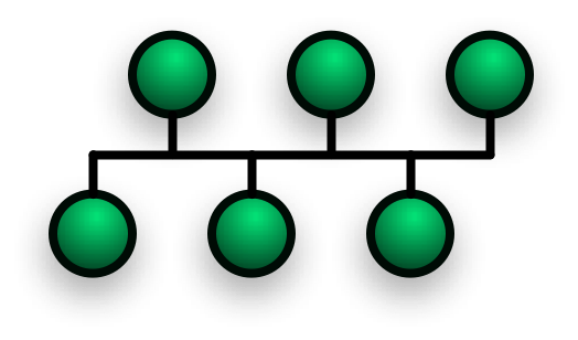
In local area networks where bus topology is used, each machine is connected to a single cable. Each computer or server is connected to the single bus cable through some kind of connector. A terminator is required at each end of the bus cable to prevent the signal from bouncing back and forth on the bus cable. A signal from the source travels in both directions to all machines connected on the bus cable until it finds the MAC address or IP address on the network that is the intended recipient. If the machine address does not match the intended address for the data, the machine ignores the data. Alternatively, if the data does match the machine address, the data is accepted. Since the bus topology consists of only one wire, it is rather inexpensive to implement when compared to other topologies. However, the low cost of implementing the technology is offset by the high cost of managing the network. Additionally, since only one cable is utilized, it can be the single point of failure. If the network cable breaks, the entire network will be down.
- Linear bus
-
- The type of network topology in which all of the nodes of the network are connected to a common transmission medium which has exactly two endpoints (this is the 'bus', which is also commonly referred to as the (backbone,or trunk) – all data that is transmittedbetween nodes in the network is transmitted over this common transmission medium and is able to be recevisd by all nodes in the network virtually simultaneously (disregarding propagation delays)[1].
-
- Note: The two endpoints of the common transmission medium are normally terminated with a device called a terminator that exhibits the characteristic impedance of the transmission medium and which dissipates or absorbs the energy that remains in the signal to prevent the signal from being reflected or propagated back onto the transmission medium in the opposite direction, which would cause interference with and degradation of the signals on the transmission medium (See Electrical termination).
- Distributed bus
-
- The type of network topology in which all of the nodes of the network are connected to a common transmission medium which has more than two endpoints that are created by adding branches to the main section of the transmission medium – the physical distributed bus topology functions in exactly the same fashion as the physical linear bus topology (i.e., all nodes share a common transmission medium).
-
- Notes:
-
-
- 1.) All of the endpoints of the common transmission medium are normally terminated with a device called a 'terminator' (see the note under linear bus).
-
-
-
- 2.) The physical linear bus topology is sometimes considered to be a special case of the physical distributed bus topology – i.e., a distributed bus with no branching segments.
-
-
-
- 3.) The physical distributed bus topology is sometimes incorrectly referred to as a physical tree topology – however, although the physical distributed bus topology resembles the physical tree topology, it differs from the physical tree topology in that there is no central node to which any other nodes are connected, since this hierarchical functionality is replaced by the common bus.
-
Star network topology
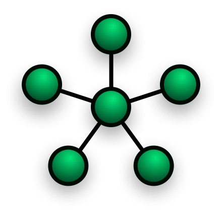
Star network topology
In local area networks with a star topology, each network host is connected to a central hub. In contrast to the bus topology, the star topology connects each node to the hub with a point-to-point connection. All traffic that transverses the network passes through the central hub. The hub acts as a signal booster or repeater. The star topology is considered the easiest topology to design and implement. An advantage of the star topology is the simplicity of adding additional nodes. The primary disadvantage of the star topology is that the hub represents a single point of failure.
Notes
- A point-to-point link (described above) is sometimes categorized as a special instance of the physical star topology – therefore, the simplest type of network that is based upon the physical star topology would consist of one node with a single point-to-point link to a second node, the choice of which node is the 'hub' and which node is the 'spoke' being arbitrary[1].
- After the special case of the point-to-point link, as in note 1.) above, the next simplest type of network that is based upon the physical star topology would consist of one central node – the 'hub' – with two separate point-to-point links to two peripheral nodes – the 'spokes'.
- Although most networks that are based upon the physical star topology are commonly implemented using a special device such as a hub or switch as the central node (i.e., the 'hub' of the star), it is also possible to implement a network that is based upon the physical star topology using a computer or even a simple common connection point as the 'hub' or central node – however, since many illustrations of the physical star network topology depict the central node as one of these special devices, some confusion is possible, since this practice may lead to the misconception that a physical star network requires the central node to be one of these special devices, which is not true because a simple network consisting of three computers connected as in note 2.) above also has the topology of the physical star.
- Star networks may also be described as either broadcast multi-access or nonbroadcast multi-access (NBMA), depending on whether the technology of the network either automatically propagates a signal at the hub to all spokes, or only addresses individual spokes with each communication.
Extended star
A type of network topology in which a network that is based upon the physical star topology has one or more repeaters between the central node (the 'hub' of the star) and the peripheral or 'spoke' nodes, the repeaters being used to extend the maximum transmission distance of the point-to-point links between the central node and the peripheral nodes beyond that which is supported by the transmitter power of the central node or beyond that which is supported by the standard upon which the physical layer of the physical star network is based.
If the repeaters in a network that is based upon the physical extended star topology are replaced with hubs or switches, then a hybrid network topology is created that is referred to as a physical hierarchical star topology, although some texts make no distinction between the two topologies.
Distributed Star
A type of network topology that is composed of individual networks that are based upon the physical star topology connected together in a linear fashion – i.e., 'daisy-chained' – with no central or top level connection point (e.g., two or more 'stacked' hubs, along with their associated star connected nodes or 'spokes').